Switch Questions
Question 1
Explanation
The command “mac address-table aging-time 180” specifies the time before an entry ages out and is discarded from the MAC address table. The default is 300 seconds. Entering the value 0 disables the MAC aging.
Question 2
Question 3
Explanation
The switch learns which port the host is attaching by examining the source MAC address in frames received on a port. For example switch receives a frame with source MAC of 0000.0000.aaaa (abbreviated as “aaaa”) on port Fa0/1, it populates its MAC address-table with an entry like this “host aaaa on Fa0/1”. If the switch receives a frame with the same “aaaa” MAC from Fa0/2 then there will be a flap and the switch will log something like this:
| %MAC_MOVE-SP-4-NOTIF: Host 0000.0000.aaaa in vlan 1 is flapping between port 0/1 and port 0/2 |
This flapping phenomenon may be the result of a Layer loop somewhere in your network, especially when STP is disabled for some reasons.
If you don’t want to see this message then issue the “no mac-address-table notification mac-move” or place a static entry with the “mac-address-table static 000.0000.aaaa vlan 1 interface fa0/1″on the switch. The command “mac-address-table notification mac-move” is disabled by default on 6500 & 7600 series but enabled by default on other series.
Question 4
Explanation
The command “show mac address-table” displays the MAC address table along with the port associated for the switch. The ‘show mac address-table address ” gives a more specific view of a specific MAC address.
Question 5
Question 6
Question 7
Question 8
Explanation
If an access port receives a tagged packet (Inter-Switch Link [ISL] or IEEE 802.1Q tagged), the packet is dropped, and the source address is not learned.
Question 9
Question 10
Explanation
The Portfast feature can be configured on both access or trunk port. This feature instructs the port to skip listening and learning state and move to forwarding state immediately.
The voice VLAN feature enables access ports to carry IP voice traffic from an IP phone. The simple example below shows how to configure voice VLAN on an interface:
| interface fastethernet0/1 switchport access vlan 10 switchport voice vlan 20 |
Note: This is not a trunk port (although two VLANs are configured on an interface). Cisco calls this a Multi-Vlan access port.
Question 11
Explanation
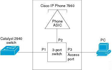
An IP phone contains an integrated three-port 10/100 switch. The ports, which are dedicated connections, are described as follows:
* Port 1 connects to the Catalyst series switch or other device that supports Voice-over-IP (VoIP).
* Port 2 is an internal 10/100 interface that carries the phone traffic.
* Port 3 connects to a PC or other device.

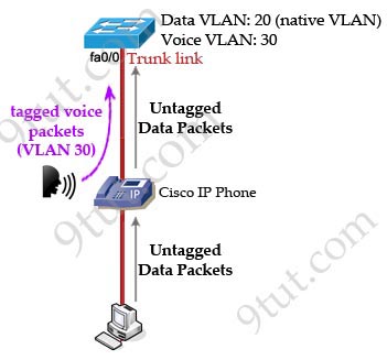
To enhance the quality of the VoIP traffic, port 2 and port 3 are often placed in two different VLANs. The VLAN carries voice traffic to and from the IP Phone is often called auxiliary VLAN (Port 2 in this case) while the VLAN carries data traffic is often the native VLAN (Port 3 in this case).
In the picture below the auxiliary VLAN is VLAN 30 while the native VLAN is VLAN 20. To use the IP Phone these two VLANs will need to be configured on the switch.

To learn how to configure auxiliary VLAN please read: http://www.cisco.com/en/US/docs/switches/lan/catalyst4000/8.1/configuration/guide/vlans.html#wp1048863.
To learn how to configure voice and data VLAN please read: http://www.cisco.com/en/US/products/hw/switches/ps4324/products_configuration_example09186a0080722cdb.shtml.
Question 12


